PHONE: 06 874 9077 | HOURS: MONDAY-FRIDAY 9AM-5PM
PHONE: 06 874 9077 | HOURS: MONDAY-FRIDAY 9AM-5PM
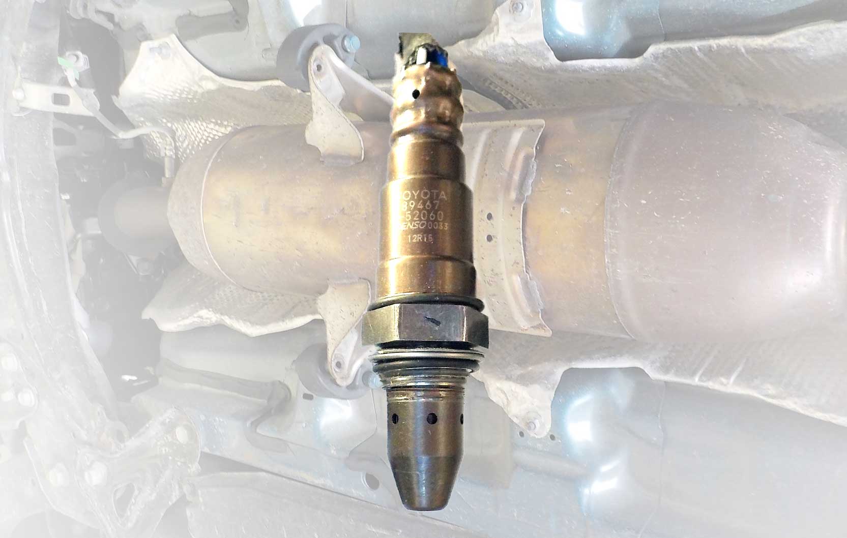
Broadband Oxygen Sensor Diagnostics is cutting edge and looks into technologies in current cars. We will train you in first-shot diagnostics, working with a scope and scan tool as your primary weapons to remove the guesswork for broadband oxygen diagnostics.
COURSE ID: EMS1-6
DURATION: 3 DAYS
Prerequisites: It is prefered that you have completed Firstline Diagnostics (EMS1-1) or Modern Petrol Engine Control (EMS1-3).
Equipment: This training is scan tool and scope based. Please bring your own scope & scan tool or if you don’t have one, AECS can provide one for the training seminar.
Emissions
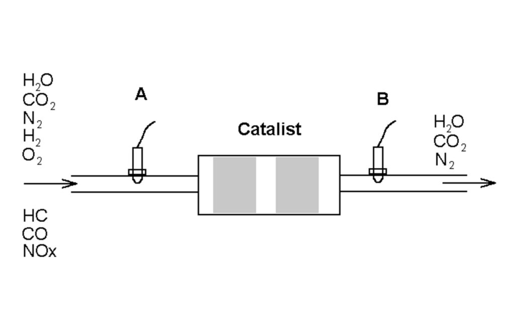
In this training, we will teach you the chemical background of emissions on the pre-cat and post-cat. We discuss in detail what the catalytic converter’s function is and what the A/F sensor and post-cat sensor measure.
We will talk about what affects contaminated sensors and how to analyse the difference between contaminated sensors or a damaged cat.
Within this component of the training, we’ll discuss what mixture the ECU is trying to achieve and why.
A/F Sensor Heater Circuits
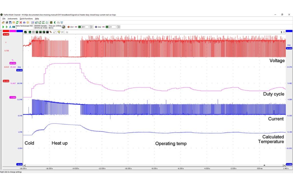
We discuss why the temperature is carefully controlled during warm-up and operation, and how this is achieved. We’ll show you what you should read from the scan tool and scope to assist in analysing the temperature control circuit.
We’ll share how and why the ECU measures the temperature in the A/F sensor to precisely 650°C within 10 seconds. Including how to see if the temperature is closed-loop controlled or will possibly fail.
A/F Sensor Circuit Layout
Understanding scan tool values is important. We’ll discuss this in regards to the circuit inside the ECU (16bit ADC and opamp) however, the voltage measured at the sensor can be different to what a scan tool displays, we will share further and why. This includes how the ECU pushes or pulls current to the sensor circuit.
O2 Sensor Inside
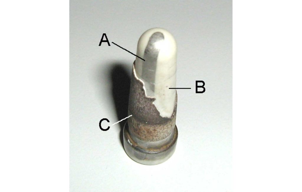
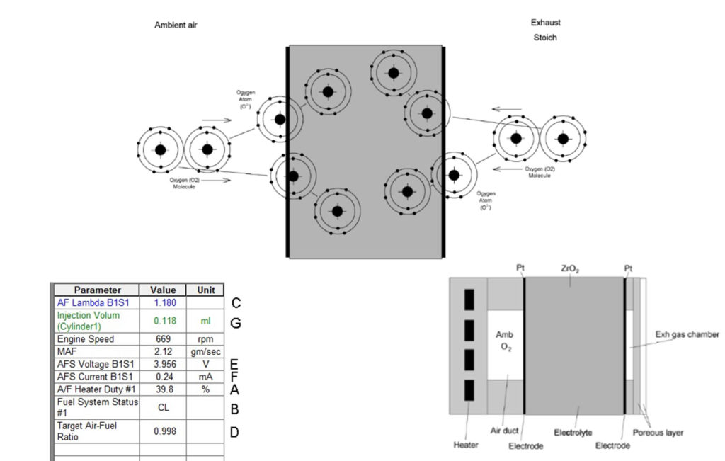
We’ll take a look at the inside of an O2 sensor, how it is built and produces an electrochemical signal. Our starting point will be to review and explain the old fashioned Zirconia dioxide 1V sensor as during diagnostics of the system including the catalyst and rear 02 sensor, this becomes very important.
A/F Sensor Inside
We’ll discuss the inside of the Zirconia Dioxide A/F sensor from the diffusion chamber to the ambient chamber. Knowing this will assist with understanding the response time of the sensor and how this relates to the scope and scan tool readings.
Every aspect of scan tool reading related to the mixture control will be covered in-depth, including the relation to emission values and scope readings.
We will share about calculated load, MAF and injection volume, how this fits into mixture control diagnostics and how the ECU calculates this. We’ll discuss what this means and how to recognise it when it’s wrong.

Long/Short Fuel Trim Diagnostics
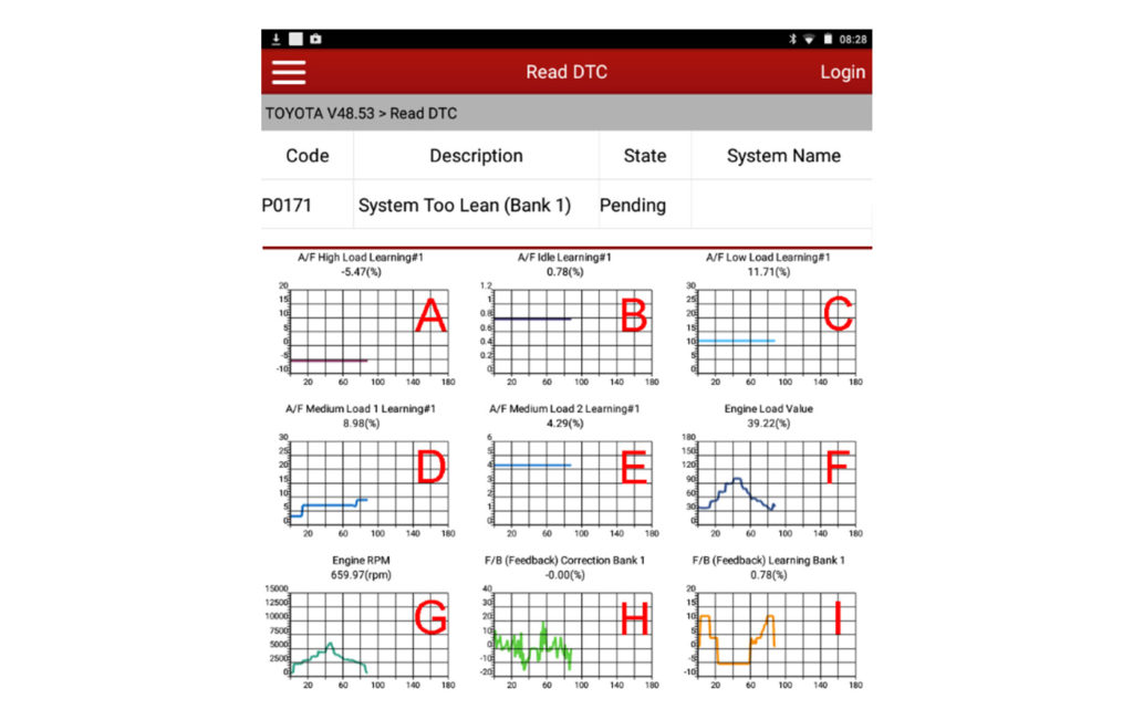
In long/short fuel trim diagnostics we’ll set the foundation by looking at LFT and SFT on 1V Zirconia dioxide sensor system. We will cover this in detail and from there, the LFT and SFT diagnostics on an A/F sensor system is just a simple step up. Included, we will discuss what the adaption values mean in different fuelling modes and what it shows you.
A/F Sensor System LFT and SFT
We’ll continue the conversation on LFT and SFT values and what they mean in an A/F sensor system, and how this knowledge crosses over.
We’ll discuss what changes in the readings when something goes wrong in the engine and how to interpret fault codes.
Several codes triggering faults will be introduced to our training simulator and these will be analysed by you including a failed ECU. We will include faults such as mixture control which will affect drivability, CVT or cam timing fault (makes a vehicle surge) and will affect the emissions of the vehicle without generating a fault code. Each scenario will be analysed and we deal in detail with the most difficult to analyse fault codes, such as the P2196 oxygen sensor stuck on rich.
Fuelling Modes
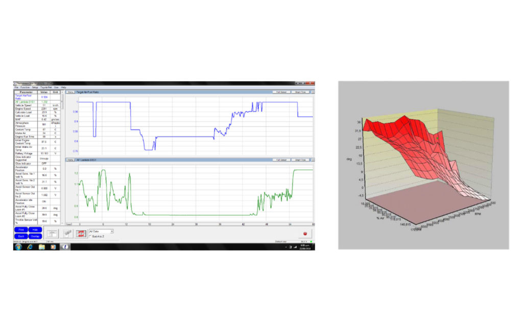
A number of different fuelling modes will be discussed and how the importance of certain sensors and faults will vary per fuelling mode. We’ll show you how the ECU switches through fuelling modes and how this affects your diagnosis.
On Car Testing
We’ll show how to test the response rate and effectiveness of the A/F sensor on a vehicle. The approach is very innovative and accurate.
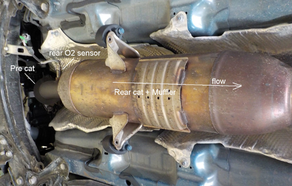
This includes analysing the mixture control, A/F sensor, catalyst and the rear O2 sensor.
Admittance Diagnostics
The ECU checks for the A/F sensor for admittance, we will show you what this means and how you can analyse the values.
Catalyst Temperature
The scan tool reads/calculates two catalyst temperatures, we’ll discuss what this means and what the values are used for.
Other Systems
The primary part of this training is using a 2015 Toyota system as an example, we will look at other brands and use the knowledge learnt to cross-train on these systems.
Video with actual EMS1-6 training content
The team at AECS are here to help. Let us know how we can be of assistance.